E-mail Us: market1@hotoheat.com Call Us On: +86-15366416606

- All
- Product Name
- Product Keyword
- Product Model
- Product Summary
- Product Description
- Multi Field Search
Views: 0 Author: Site Editor Publish Time: 2026-07-19 Origin: Site
Improperly specified heating systems lead to accelerated thermal fluid degradation, premature element burnout, and costly unplanned facility downtime. Engineers and plant managers must balance the need for rapid, efficient heat transfer with the strict thermal limits of industrial oils. Exceeding these limits causes "coking" (carbon buildup), which destroys both the fluid and the heater.
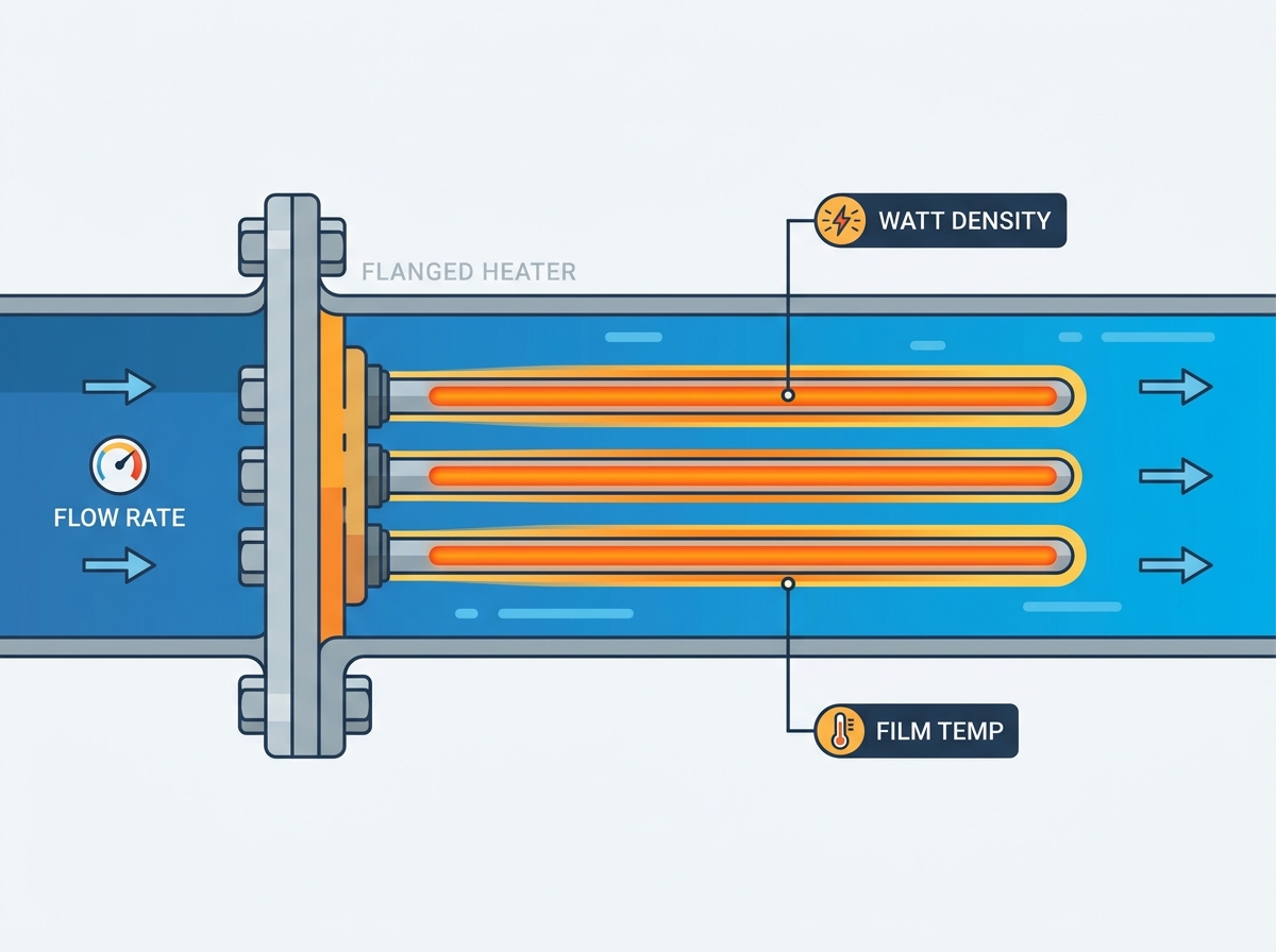
Preventing system failure requires a precise mathematical and operational balance between watt density, fluid flow rate, and film temperature. You cannot simply drop a high-output heater into a tank of oil and expect it to run indefinitely. The fluid dynamics must match the thermal output. This guide details the engineering frameworks required to evaluate and specify flanged electric heaters for heat transfer oil to ensure long-term reliability, process safety, and maximum equipment lifespan.
Watt density is not a standalone metric: Standard watt density charts are only starting points; actual allowable watt density must be dynamically adjusted based on fluid velocity and specific heat transfer coefficients.
Flow rate dictates thermal safety: Higher fluid velocities increase the convection coefficient, pulling heat away from the element faster and allowing for higher watt densities without exceeding safe film temperatures.
Film temperature is the ultimate limiting factor: The temperature of the fluid immediately adjacent to the heater sheath must never exceed the fluid manufacturer’s maximum allowable film temperature, regardless of the bulk fluid temperature.
System design requires holistic evaluation: Specifying flanged electric heaters requires analyzing pumpability, pressure drop, fluid viscosity at startup, and advanced control staging to mitigate implementation risks.
Heat transfer begins deep inside the heater element. Thermal energy conducts from the internal nickel-chromium resistance wire through the dielectric insulation to the outer metal sheath. Manufacturers use compacted magnesium oxide (MgO) for this insulation. The compaction process is highly specific; elements are rolled or swaged to compress the MgO powder into a dense solid. This density maximizes thermal conductivity while maintaining electrical isolation. If the MgO is loosely packed, air pockets form. Air is a poor thermal conductor, which forces the internal wire temperature to spike, leading to rapid element failure.
Once heat reaches the outer metal sheath, it transfers into the fluid primarily via forced convection. The fluid moving across the element absorbs the heat and carries it into the process loop. Radiation also plays a secondary role, especially at elevated sheath temperatures. You must address the extreme risk of radiant heat buildup under stagnant fluid conditions or "dry-firing" events. If the pump fails and the heater remains energized, the absence of moving fluid causes the sheath temperature to climb hundreds of degrees in seconds, destroying the elements and potentially igniting the fluid.
Thermal transfer fluids react aggressively to localized heat flux. When you apply heat too rapidly, the fluid breaks down chemically. The long hydrocarbon chains crack into smaller, volatile molecules and heavy carbon residues. This degradation reduces the fluid's ability to transfer heat, lowers its flash point, and shortens its usable lifespan.
Four critical fluid performance criteria govern the selection of heating equipment. First, the operating temperature range dictates the base thermal load. Second, fluid pumpability (viscosity) determines how fast you can move the oil across the elements. Third, system operating and vapor pressure dictate the mechanical strength required for the vessel and flanges. Finally, thermal stability limits define the absolute maximum temperature the fluid can withstand before cracking. Evaluating these factors ensures that the selected heater matches the physical and chemical constraints of the specific thermal oil.
Flanged heaters allow for direct, highly efficient heat transfer within circulation tanks or pressure vessels. Because the heating elements are immersed directly in the fluid, nearly 100% of the generated heat enters the process. There are no exhaust stack losses or burner inefficiencies to account for.
Engineers evaluate these heaters based on ease of installation, compatibility with ANSI standard flanges, and the ability to bundle multiple elements for high-kilowatt applications. The flanged design simplifies maintenance. You can unbolt the flange, pull the entire element bundle out of the vessel, and replace it without cutting pipes or performing extensive vessel modifications. Standard ANSI flanges (such as 150# or 300# ratings) ensure compatibility with existing piping infrastructure.
Proper installation requires specific steps to ensure a leak-free and thermally sound connection:
Verify the flange rating matches the vessel's design pressure and temperature.
Inspect the mating flange face for scratches, pitting, or debris that could compromise the gasket seal.
Select a high-temperature gasket, typically a spiral-wound graphite gasket, rated for the specific thermal oil.
Insert the heater bundle carefully, ensuring the elements do not scrape against the vessel walls or internal baffles.
Tighten the flange bolts using a star pattern and a calibrated torque wrench to achieve uniform gasket compression.
Direct immersion heaters provide high efficiency, rapid response times, and a compact footprint. They are the preferred choice when precise temperature control and fast heat-up times are required. The direct contact between the sheath and the fluid ensures immediate heat transfer.
Indirect methods, such as pipe inserts or bayonet heaters, offer ease of maintenance since elements can be replaced without draining the system. The heating element sits inside a dry pipe, and the pipe transfers heat to the fluid. However, this convenience is balanced against lower heat transfer efficiency and larger footprint requirements. The heat must cross an additional air gap and metal barrier before reaching the fluid. Use relative heater sheath temperature and process fluid characteristics to decide between direct flanged immersion and indirect configurations.
Evaluation Metric | Direct Flanged Immersion | Indirect (Pipe Insert/Bayonet) |
|---|---|---|
Heat Transfer Efficiency | High (~100%) | Moderate (Losses across air gap) |
Maintenance Procedure | Requires draining the vessel | Elements replaced without draining |
Physical Footprint | Compact | Larger (Requires more surface area) |
Thermal Response Time | Rapid | Slower (Thermal lag from outer pipe) |
Sheath Temperature Risk | Lower (Direct fluid contact) | Higher (Internal element runs hotter) |
Watt density measures the heat flux at the element sheath, expressed in Watts per square inch (W/in²). It dictates how much heat is concentrated on a given surface area of the heater. You calculate it by dividing the total wattage of the element by its active heated surface area.
Engineers use watt density as a baseline benchmark to compare the physical size, element spacing, and footprint of different heater options for the same kW output. A lower watt density generally means a larger heater bundle, which spreads the heat over a greater surface area and reduces the sheath temperature. For example, a 100 kW heater designed at 15 W/in² will be physically twice as large as a 100 kW heater designed at 30 W/in².
Excessive watt density leads to localized boiling, thermal cracking, and carbonization (coking) on the sheath surface. When the heat flux exceeds the fluid's ability to absorb and carry away the energy, the fluid directly touching the element breaks down. It forms a hard, black carbon layer baked onto the metal.
This carbon buildup acts as a powerful thermal insulator. It prevents heat from escaping into the fluid, driving internal resistance temperatures upward. The heater's internal thermocouple might not detect this immediately if it is located away from the coked area. This insulation loop inevitably causes catastrophic element burnout, splitting the metal sheath and forcing costly system shutdowns. Once an element splits, live electrical voltage can short directly to the fluid or the grounded vessel.
Holding watt density constant does not guarantee a safe sheath temperature. Internal factors significantly influence how heat moves from the wire to the sheath. Two heaters with the exact same watt density can operate at vastly different sheath temperatures.
Construction quality matters. Variables such as MgO compaction density, resistance wire gauge, coil pitch, and sheath wall thickness can cause sheath temperatures to vary by 50°F or more between manufacturers. A poorly centered resistance coil will create a hot spot on one side of the sheath. Engineers must demand application-specific thermal calculations rather than relying solely on generic watt-density charts. You need to know the exact internal thermal resistance of the specific heater design.
Stagnant hot oils require drastically restricted watt densities, often 10 W/in² or lower, to prevent localized fluid degradation. Without mechanical flow to carry heat away, the fluid relies entirely on natural convection currents. These currents are slow, meaning the fluid near the sheath quickly overheats and degrades.
In circulating systems, allowable watt density scales upward. Mechanical fluid flow accelerates heat transfer rates. The pump forces cold fluid across the elements, rapidly absorbing the heat. This allows the heater to operate at higher watt densities (often 20 to 30 W/in², depending on the fluid) while maintaining safe sheath and film temperatures.
System Type | Fluid Velocity | Typical Allowable Watt Density | Primary Heat Transfer Mode |
|---|---|---|---|
Storage Tank (Stagnant) | 0 ft/sec | 8 - 12 W/in² | Natural Convection |
Low-Flow Circulation | 1 - 3 ft/sec | 15 - 20 W/in² | Mixed Convection |
High-Flow Circulation | 4 - 7+ ft/sec | 22 - 30 W/in² | Forced Convection |
Faster-moving fluid reduces the thickness of the stagnant thermal boundary layer surrounding the heater sheath. In fluid dynamics, a thin layer of fluid always clings to the surface of the pipe or heater element. Heat must conduct through this stagnant layer before it can be swept away by the bulk fluid flow.
Increased fluid velocity lowers the sheath temperature by stripping heat away from the element more rapidly. Higher velocity creates turbulent flow, which mixes the fluid and drastically thins the boundary layer. This process keeps film temperatures within safe limits even at higher watt densities, optimizing the overall system footprint. You can push more kilowatts into a smaller vessel if you pump the fluid fast enough.
High fluid velocities require larger pumps and increase system pressure drop across the heater bundle. Engineers must balance the thermal benefits of high velocity with the mechanical costs of pumping. Forcing thick oil through a tightly packed bundle of heater elements requires significant pump head pressure.
At cold startup, high fluid viscosity limits pumpability and flow rate, creating a high-risk operational window. The fluid is thick, sometimes resembling syrup, and moves slowly. This reduces heat transfer efficiency drastically. Implementing soft-start procedures protects the fluid and heater during this critical phase.
A proper cold startup sequence involves:
Engaging the circulation pump and verifying minimum flow rates before energizing the heater.
Applying power to the heater in short pulses (time-proportional control) rather than 100% continuous output.
Monitoring the differential pressure across the heater vessel to ensure the fluid is actually moving and not bypassing the bundle.
Gradually increasing the power output as the bulk fluid temperature rises and the viscosity drops.
Switching to full PID control only after the fluid reaches its optimal pumping viscosity.
Understanding the thermal profile requires distinguishing between three distinct temperatures. The bulk temperature is the average temperature of the fluid flowing through the system. This is what your main process temperature sensor reads.
The sheath temperature is the physical surface temperature of the metal heater element. The film temperature is the critical, elevated temperature of the microscopic fluid boundary layer directly contacting the hot heater sheath. The film temperature is always higher than the bulk temperature and slightly lower than the sheath temperature.
Every heat transfer fluid has a strict maximum film temperature rating provided by the manufacturer. Exceeding this rating guarantees fluid degradation. You cannot guess this number; you must pull the technical data sheet for the specific oil you are using.
The thermal balance dictates that the film temperature equals the bulk temperature plus the temperature rise across the boundary layer. This temperature rise is a direct function of watt density and fluid velocity. Controlling these two variables is the only way to manage film temperature effectively. If your bulk temperature is 400°F and your fluid's maximum film temperature is 450°F, you only have a 50°F margin. Your watt density and flow rate must be engineered to keep the boundary layer temperature rise below 50°F.
Proper system sizing requires a comprehensive checklist. Engineers must evaluate the total heating load, separating the initial heat-up requirements from the continuous process operating load. Heat-up loads are often much higher because you are raising the temperature of the entire fluid volume and the surrounding steel piping.
Vessel volume constraints, pressure ratings, and fluid-specific properties like viscosity, specific heat, and thermal conductivity must all be factored into the final heater specification. You must also account for environmental heat losses through uninsulated pipes or tanks. Consulting with experienced thermal engineers ensures all variables are accurately assessed and the final design meets all safety codes.
Internal baffles are engineered to eliminate dead zones and prevent bypass flow. When fluid enters a circulation heater vessel, it naturally wants to take the path of least resistance, often flowing straight from the inlet to the outlet without touching the elements. Baffles force the fluid to weave back and forth across the heater bundle.
Precise baffle spacing ensures uniform heat distribution across the entire element bundle. They artificially increase localized fluid velocity across the flanged heater elements, maximizing heat transfer efficiency. This normalization prevents localized hot spots and ensures the system operates safely within the fluid's thermal limits. Baffle cuts (the percentage of the baffle that is open) must be calculated to balance fluid velocity against acceptable pressure drop.
Selecting a flanged electric heater for heat transfer oil is not simply a matter of choosing the highest available power rating. Long-term system reliability depends on maintaining the correct relationship between heater watt density, fluid velocity, and maximum allowable film temperature. When these factors are properly balanced, the heating system can deliver stable thermal performance while minimizing oil degradation, coking, and unexpected equipment failures.
A successful thermal fluid heating design requires a complete evaluation of operating conditions, including startup viscosity, circulation flow, heat transfer requirements, control strategy, and fluid thermal limits. Lower watt density may require a larger heater footprint, but it often provides greater reliability and longer service life. Likewise, optimized flow paths, proper baffling, and staged power control ensure that the heater operates within safe thermal boundaries throughout the entire process cycle.
A: Bulk temperature is the average temperature of the entire fluid volume moving through the system. Film temperature is the localized, much higher temperature of the thin fluid layer directly touching the heater sheath.
A: Coking happens when the heater's watt density is too high for the fluid's flow rate, causing the film temperature to exceed the fluid's thermal stability limit. The oil breaks down and bakes carbon onto the elements.
A: Higher fluid velocity increases the forced convection heat transfer rate. This strips heat away from the sheath faster, allowing the heater to operate safely at a higher watt density without overheating the fluid.
A: At cold startup, thermal oils are highly viscous and flow slowly. A soft-start applies reduced power initially, preventing the heater from overheating the slow-moving, thick fluid before normal operating flow rates are achieved.
A: No. Stagnant fluids require significantly lower watt densities because heat is not being mechanically carried away. Circulating fluids can handle higher watt densities due to improved convective heat transfer.