E-mail Us: market1@hotoheat.com Call Us On: +86-15366416606

- All
- Product Name
- Product Keyword
- Product Model
- Product Summary
- Product Description
- Multi Field Search
Views: 0 Author: Site Editor Publish Time: 2026-08-04 Origin: Site
Industrial electric heating requires strict thermal management; inadequate control mechanisms directly cause batch rejection, excessive energy consumption, and premature heater burnout. Engineers and facility managers must bridge the gap between process temperature requirements and electrical power delivery. Selecting the wrong combination of logic and switching leads to thermal cycling fatigue, electrical noise, or unnecessary capital expenditure. This guide breaks down the technical evaluation of electric heater control panels, detailing how to align temperature control algorithms and power switching technologies with specific industrial process requirements. We will examine the physical hardware, the control algorithms, and the integration strategies necessary to maintain precise thermal profiles across varying load dynamics.
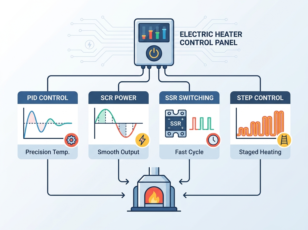
Logic vs. Switching: Effective control panel specification requires separating the temperature control logic (PID, On/Off, Step) from the physical power switching components (SSR, SCR, Electromechanical Contactors).
Precision vs. Cost Trade-offs: While PID paired with SCRs offers infinite resolution and maximum heater life, it introduces higher upfront costs and requires harmonic distortion mitigation compared to basic step control.
Heater Lifespan Impact: Fast-cycling solid-state switching (SSR/SCR) significantly reduces thermal shock and element fatigue compared to the hard cycling of electromechanical contactors.
Thermal Management is Critical: High-amperage solid-state control panels require rigorous internal cooling strategies to prevent catastrophic component failure.
A heating control loop relies on three primary components working in unison. The sensor, typically a Type J or K thermocouple or a PT100 RTD, measures the process temperature at the heat source or within the medium. The logic controller interprets this analog signal against the desired setpoint. Finally, the power switching device dictates how electrical current reaches the heating elements. Understanding this fundamental architecture helps operators diagnose thermal inconsistencies and optimize energy usage on the plant floor.
Facilities choose between dedicated standalone microprocessor controllers and PLC-based systems. Standalone controllers excel in simple, isolated loops where dedicated hardware ensures rapid response times without network latency. They are highly reliable for single-zone applications like small holding tanks or localized extrusion dies. PLC-based PID controllers integrate into complex plant environments. They manage multi-zone systems, handle complex sequencing, and share data across facility networks. The choice depends entirely on process complexity, zone count, and data collection requirements.
Controller Architecture | Primary Advantage | Typical Application | Integration Level |
|---|---|---|---|
Standalone Microprocessor | Isolated reliability, fast local response | Single-zone tanks, localized dies | Low to Medium (Modbus RTU) |
PLC-Based PID | Multi-zone coordination, complex logic | Large continuous flow systems, multi-stage reactors | High (Ethernet/IP, SCADA) |
Physical wiring within these panels requires precise execution to prevent signal degradation. A low-voltage DC control signal, often 4-20mA or 0-10VDC, travels from the PID controller to the high-voltage AC solid-state switching device. This separation protects sensitive logic components from high-voltage spikes. Proper routing, including the use of shielded twisted-pair cables for sensor inputs and maintaining physical distance between high-voltage power lines and low-voltage signal wires, minimizes electromagnetic interference and ensures stable signal transmission across the panel.
System integration determines overall reliability. Components reside within NEMA-rated enclosures designed for specific environmental hazards, such as NEMA 4X for washdown areas or NEMA 12 for dusty indoor environments. Semiconductor-rated fast-acting fuses (I2T fuses) protect solid-state relays from short circuits, reacting much faster than standard breakers. Safety interlocks shut down power during abnormal conditions, such as low flow or high pressure. A successful implementation achieves temperature stability, maximizes component longevity, meets safety compliance, and simplifies routine maintenance procedures.
On/Off control utilizes a simple hysteresis loop. Power operates at either 100% capacity or completely shuts off based on a predefined deadband. This binary approach causes severe thermal cycling. Temperatures inevitably overshoot the setpoint as residual heat transfers from the element to the process, leading to accelerated wear on heating elements due to constant expansion and contraction. You should only apply this logic to large-mass systems where temperatures change very slowly, such as massive water storage tanks. Basic freeze protection setups often rely on this simple mechanism because precise temperature maintenance is not required.
Step control divides the total heater load into multiple independent circuits or stages. The controller activates these stages sequentially as thermal demand increases. This method proves highly effective for very large kilowatt loads, such as large duct heaters or massive circulation systems. It significantly reduces massive inrush currents associated with activating a massive heater simultaneously, which can cause voltage drops across the facility. However, step control lacks fine-tuned precision. It relies heavily on electromechanical contactors, which possess finite mechanical lifespans and require regular replacement due to contact pitting and wear.
Stage 1 activates at 10 degrees below setpoint to provide baseline heat.
Stage 2 activates at 20 degrees below setpoint for moderate demand.
Stage 3 activates at 30 degrees below setpoint for maximum recovery.
Stages deactivate in reverse order as the process approaches the target temperature.
PID control uses advanced mathematical algorithms to calculate precise power requirements. It anticipates temperature changes and actively prevents overshoot. The Proportional band adjusts power based on the distance from the setpoint. The Integral action corrects long-term offsets, ensuring the temperature eventually hits the exact target. The Derivative action monitors the rate of temperature change, slowing down the heat input if the temperature rises too quickly. This logic delivers flat-line temperature stability, maximizing product yield in sensitive industrial processes like chemical blending or semiconductor manufacturing.
Implementation requires accurate tuning. Operators must calculate proportional, integral, and derivative parameters to match the specific thermal lag of the process. Modern controllers often feature auto-tune capabilities to simplify this calibration. During an auto-tune cycle, the controller forces the system to oscillate around the setpoint, measuring the thermal response time and automatically calculating the optimal PID values. Manual tuning remains necessary for highly dynamic loads where auto-tune algorithms struggle to establish a stable baseline.
Selecting the right switching technology directly impacts heater longevity and process precision. The physical mechanism must align with the chosen control logic. Mismatching a fast-acting PID controller with a slow mechanical contactor negates the benefits of the advanced logic.
Electromechanical contactors use physical metal contacts, often made of silver-cadmium oxide, to open and close circuits. They generate minimal heat inside the panel, simplifying enclosure cooling requirements. However, their slow cycle times make them incompatible with precise PID control. They typically cycle every 15 to 30 seconds. The physical movement results in a high mechanical failure rate over time, demanding frequent maintenance interventions. Every time the contacts open under load, a small electrical arc occurs, slowly degrading the contact surface until it eventually welds shut or fails to conduct.
Solid State Relays provide semiconductor-based switching without moving parts. They typically utilize zero-cross switching, activating power only when the AC voltage sine wave crosses the zero-voltage point. This allows for extremely fast cycle times, often under one second, without generating significant electrical noise. SSRs eliminate arcing and mechanical wear entirely. They represent the industry standard for most precision electric heater control panels. Because they switch so rapidly, they keep the heating element at a constant, steady temperature, drastically reducing thermal fatigue and extending element life.
Silicon Controlled Rectifiers are advanced solid-state devices capable of handling massive amperages. They utilize phase-angle firing to chop the AC waveform, delivering a precise percentage of continuous power rather than pulsing on and off. This provides infinite resolution and maximizes heating element lifespan by eliminating thermal shock entirely. They excel in low-mass applications like short-wave infrared lamps, which react instantly to power changes. However, phase-angle firing generates significant electrical noise and harmonics. Facilities must install specialized filtering, such as line reactors, to mitigate this distortion and protect other sensitive equipment on the same power grid.
Switching Technology | Cycle Time | Mechanical Wear | Ideal Application |
|---|---|---|---|
Electromechanical Contactor | 15-30 seconds | High | Basic On/Off, Step Control |
Solid State Relay (SSR) | < 1 second | None | Standard PID Control |
Silicon Controlled Rectifier (SCR) | Continuous (Phase-Angle) | None | High-Precision, Low-Mass Heaters |
High-power industrial panels require careful evaluation of three-phase configurations. Engineers must choose between 1-phase, 2-phase (3-phase/2-leg control), and 3-phase (3-phase/3-leg control) setups. In a 3-phase/2-leg configuration, two lines are switched via solid-state devices while the third line remains unswitched. This reduces component costs and panel heat but is only suitable for balanced loads. A 3-phase/3-leg configuration switches all three lines, providing maximum control and safety, and is strictly required for unbalanced loads or systems wired in a grounded Wye configuration. Proper configuration ensures even power distribution and prevents premature component degradation.
Resistive loads and inductive loads dictate different switching choices. Electric heaters are almost exclusively resistive loads, meaning current and voltage remain in phase. Low-mass surface applications, like trace heating tapes on long pipe runs, require highly responsive, localized microprocessor controls to prevent localized hot spots. Conversely, high-mass heavy industrial immersion heaters demand robust power handling capabilities. Rapid thermal expansion and contraction cause the magnesium oxide insulation inside tubular elements to break down, leading to element failure. Implementing SSR or SCR switching mitigates this thermal shock, extending the operational life of the equipment by maintaining a steady sheath temperature.
Operators must evaluate load dynamics before specifying a panel. Static loads maintain constant flow and mass, allowing for simpler control strategies. For example, a holding tank that maintains a batch of oil at a constant temperature with no new product entering the system represents a static load. Dynamic loads involve variable flow or mass, such as an inline circulation heater where the fluid flow rate changes based on downstream demand. These dynamic environments strictly require PID and SCR combinations to maintain stability. Failing to match the control strategy to load variance results in erratic temperature fluctuations and potential product spoilage.
Multi-zone heating systems require scalable architectures. Facilities must evaluate discrete temperature controllers against integrated PLC-based loops. Modern panels utilize communication protocols like Modbus RTU over RS-485 or Ethernet/IP. This connectivity allows integration into broader SCADA systems, enabling centralized monitoring, remote setpoint adjustment, and comprehensive data logging for compliance reporting. When specifying a panel for a facility with existing automation, ensuring protocol compatibility prevents costly integration delays and requires fewer standalone data acquisition modules.
Solid-state relays and SCRs generate significant internal heat due to voltage drops across the semiconductor junctions. They typically produce 1 to 1.5 watts of heat per amp per phase. For a 100-amp, three-phase heater, the panel must dissipate roughly 300 to 450 watts of heat. Without proper thermal management, this heat causes catastrophic component failure. Engineers must specify appropriately sized aluminum heat sinks. Forced-air cooling fans and strategic panel ventilation prevent thermal runaway. In extremely harsh environments where vented panels are not permitted, closed-loop air conditioners or air-to-water heat exchangers must be mounted to the enclosure to maintain safe internal operating temperatures.
SCR phase-angle firing introduces Total Harmonic Distortion (THD) into the facility power grid. This electrical noise disrupts sensitive equipment, causes erratic sensor readings, and can overheat facility transformers. Specifying zero-cross SSRs eliminates this risk in most applications because they only switch when voltage is at zero. When phase-angle SCRs remain mandatory for process reasons, facilities must install line reactors and harmonic filters upstream of the control panel to protect overall power quality and comply with IEEE 519 standards regarding harmonic limits.
Robust alarm loop design protects personnel and equipment from catastrophic failures. Loop Break Alarms (LBA) detect sensor detachment or failure immediately, shutting down power before the controller drives the heater to maximum output in a blind attempt to reach the setpoint. Deviation alarms monitor high and low limits, alerting operators if the process drifts outside acceptable parameters. Current Transmitter (CT) feedback detects partial element failures by monitoring amperage draw, identifying a burned-out element even if the overall temperature remains stable. Mandatory independent high-limit temperature controllers, typically FM approved, cut power via a separate mechanical contactor during solid-state failures. This is critical because SSRs and SCRs typically fail in the "closed" or "on" position, which would otherwise cause a runaway heating event. Ensure NEMA enclosure ratings match the operating environment exactly to prevent moisture or dust ingress from compromising the high-voltage components.
The choice between Step, SSR, and SCR control requires matching switching speed and logic precision to the thermal mass and tolerance of your specific process. Choose Step Control for massive, slow-moving thermal loads where budget constraints override the need for tight precision. Select PID with zero-cross SSRs as the standard for most industrial applications to balance cost, precision, and heater lifespan. Reserve PID with phase-angle SCRs for low-mass heaters requiring infinite resolution and rapid response times.
Audit current heater failure rates to identify thermal cycling issues caused by mechanical contactors.
Evaluate process deviations and scrap rates to determine the ROI for upgrading to a PID-based control panel.
Assess panel installation environments to ensure proper NEMA ratings and calculate necessary cooling requirements for solid-state components.
Contact a thermal engineering specialist to specify a custom panel tailored to your facility's exact electrical and environmental constraints.
A: Solid State Relays (SSR) typically use zero-cross switching, turning power on or off completely at fast intervals without generating electrical noise. Silicon Controlled Rectifiers (SCR) can use phase-angle firing, chopping the AC waveform to deliver a continuous, precise percentage of power, offering infinite resolution for highly sensitive, low-mass loads.
A: A PID controller calculates exact power needs to maintain a setpoint without overshooting. On/Off switches cause severe temperature fluctuations and thermal shock, which degrades heating elements quickly. PID ensures flat-line stability, improves product quality, and significantly extends equipment life.
A: Step control divides a large heating load into smaller, independent circuits. As temperature demand increases, the controller turns on these stages sequentially using mechanical contactors. This prevents massive electrical inrush currents on the facility grid but lacks the fine precision of PID control.
A: Yes, SSRs are commonly used in three-phase heating circuits. You can configure them in 2-leg or 3-leg control setups depending on whether the electrical load is balanced or unbalanced, providing fast, wear-free switching for industrial heaters.
A: Solid-state components like SSRs and SCRs generate heat during operation, typically 1 to 1.5 watts per amp per phase. Without heat sinks and cooling fans, this heat accumulates inside the enclosure, leading to thermal runaway and catastrophic component failure.