E-mail Us: market1@hotoheat.com Call Us On: +86-15366416606

- All
- Product Name
- Product Keyword
- Product Model
- Product Summary
- Product Description
- Multi Field Search
Views: 0 Author: Site Editor Publish Time: 2026-07-29 Origin: Site
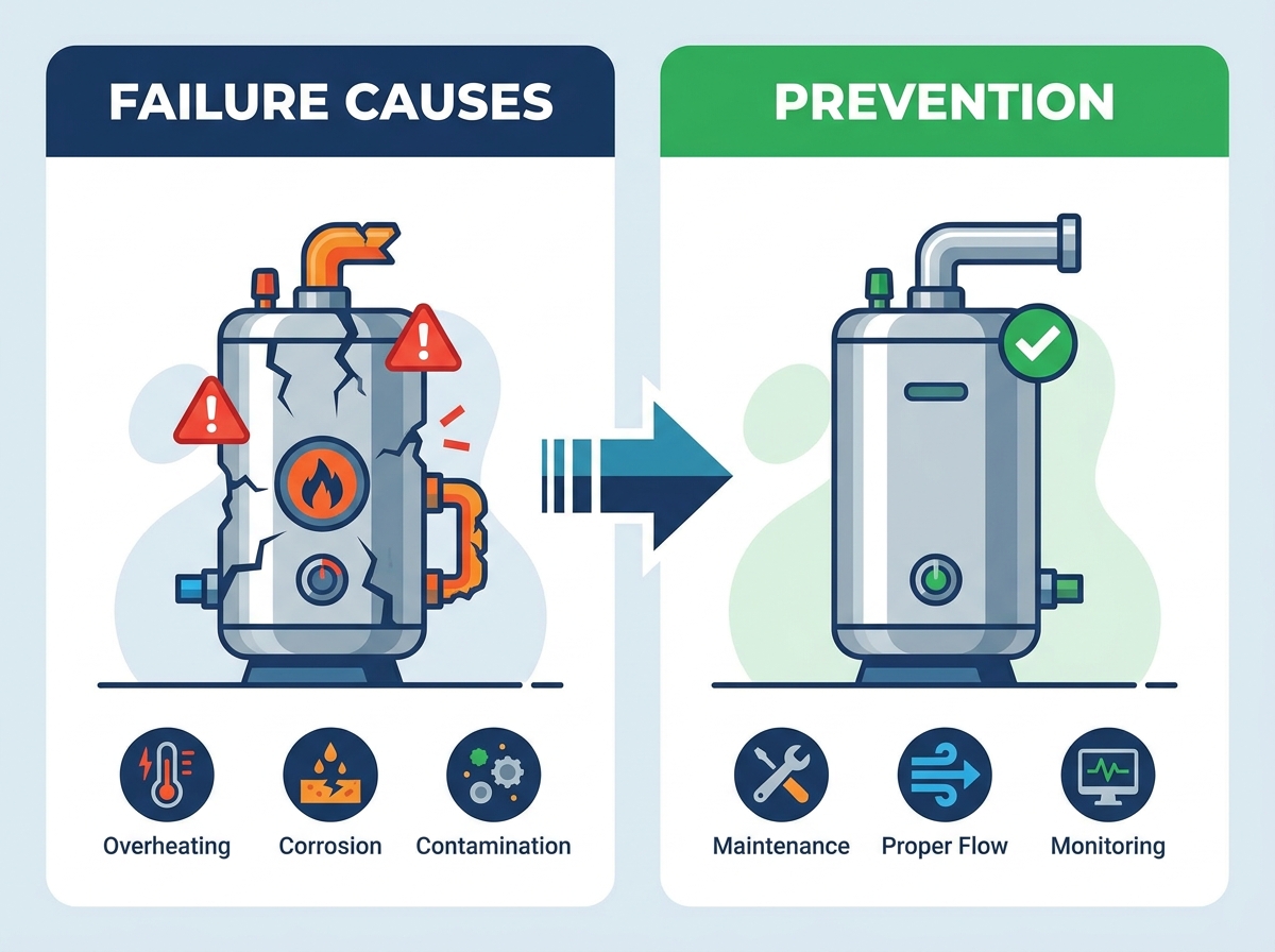
Premature equipment failure disrupts production schedules and inflates maintenance budgets. When a heating system goes down, the entire process line halts. The lifespan of an industrial circulation heater is not just a maintenance metric. It is a critical factor in overall plant uptime, energy efficiency, and capital expenditure planning. Most heater failures are predictable and preventable. By applying rigorous specification, proper installation, and proactive control strategies, facility managers can significantly extend equipment life. You must understand the financial impact of premature failures, the primary root causes of system degradation, and actionable prevention methods to keep operations running smoothly.
Watt Density is Critical: Operating an industrial circulation heater beyond its specified watt density—often due to over-voltage—rapidly accelerates sheath degradation and insulation breakdown.
Flow Dynamics and Pressure Dictate Lifespan: Inadequate flow rates, dry firing, fluid flashing, and fouling create localized hotspots and pressure stresses that compromise metallurgical and structural integrity.
Control Systems Matter: Short cycling and sensor failures cause premature wear on both the heating elements and the electrical contactors.
Specification Drives Longevity: Aligning sheath material, pressure ratings, and watt density with the specific fluid chemistry, pressure limits, and operating temperature is the most effective preventative measure.
The true cost of equipment failure extends far beyond the replacement price of the hardware. When an industrial circulation heater fails, facilities face lost production time, emergency labor rates, and wasted energy. Inefficient, fouled elements draw excessive power while failing to transfer heat effectively into the fluid medium. This inefficiency degrades operational margins long before the heater actually burns out. Plant managers often underestimate the compounding costs of running degraded equipment.
A failing heater consumes more power to achieve the same temperature rise. Scale buildup acts as a thermal insulator. This barrier hinders efficient thermal transfer, forcing the system to work harder. Consequently, energy bills rise while process temperatures remain unstable. The financial drain is continuous and often goes unnoticed until a catastrophic failure occurs. You end up paying for electricity that simply heats up a layer of baked-on calcium instead of your process fluid.
Catastrophic failures introduce severe safety and compliance risks. Fluid leaks, electrical shorts, and pressure vessel ruptures endanger personnel and damage adjacent equipment. Operating compromised pressure vessels can lead to violations of safety standards like ASME, NEC, and OSHA. Maintaining equipment integrity is essential for safe, compliant, and profitable plant operations. An unexpected rupture can shut down a facility for weeks pending safety investigations.
Failure Type | Direct Costs | Indirect Costs | Safety Risk Level |
|---|---|---|---|
Element Burnout | Replacement flange bundle, labor | Process downtime, scrapped batches | Low to Medium |
Sheath Rupture | Full vessel replacement, fluid cleanup | Environmental fines, extended downtime | High |
Ground Fault | Electrical component replacement | Power grid disruption, control panel damage | High |
Mineral deposits in water or coking in hydrocarbon oils bake directly onto the heater sheath. This buildup acts as a stubborn thermal barrier. It severely inhibits efficient conductive and convective heat transfer into the surrounding fluid. The process medium remains cooler than intended while the heater works continuously. We see this constantly in hard water applications where filtration is ignored.
This buildup acts as thermal insulation around the element. It forces the internal resistance wire to operate at excessively high temperatures. Eventually, the internal wire overheats, becomes brittle, and burns out completely. The sheath itself may also split or deform under extreme thermal stress. Once the sheath splits, fluid enters the element, causing an immediate dead short to ground.
Preventing this requires strict adherence to regular maintenance schedules. Implement fluid filtration systems to remove particulates before they reach the heating vessel. Always select a lower watt density for fluids that are highly prone to fouling or coking. For heavy fuel oils, keep watt densities below 15 W/in² to prevent the oil from carbonizing on the elements.
Applying a voltage higher than the rated capacity of the heater creates immediate problems. Wattage output increases exponentially with voltage. A small increase in supply voltage leads to a massive spike in total heat generation. This overpowers the physical design limits of the heating elements. A heater rated for 480V will destroy itself quickly if fed 520V.
This resulting spike in watt density raises the sheath temperature rapidly. The extreme heat accelerates the dielectric breakdown of the magnesium oxide insulation inside the element. Once the insulation fails, the internal wire shorts to the outer sheath, destroying the heater instantly. Magnesium oxide loses its insulating properties rapidly when pushed past its thermal limits.
Conduct rigorous electrical infrastructure audits regularly. Use voltage regulators to ensure stable power delivery. Verify that the specified heater is explicitly rated for the facility's actual, measured supply voltage, not just the nominal rating. Check the incoming voltage at the contactor under load to get an accurate reading.
Fluid velocity must remain above the minimum required rate for safe operation. If flow drops, the heater operates without adequate fluid to carry the heat away. Sudden pressure drops can also cause the liquid to flash into gas, creating vapor pockets around the elements. Vapor transfers heat poorly compared to liquid.
These scenarios cause the rapid onset of extreme localized heating. Poor heat transfer leads to immediate sheath melting and element rupture. In systems heating volatile fluids, dry firing or flashing can even lead to fluid ignition and severe fires. We have seen entire skids melt down because a pump failed and the heater kept running.
Mandate the integration of flow switches and liquid level sensors. Install pump interlocks within the control panel. These safety devices must automatically disable the heater if flow is interrupted or if system pressure drops below flash-point thresholds. Never rely on manual intervention to shut down a heater during a loss-of-flow event.
Short cycling is the rapid, continuous turning on and off of the heater. This happens due to oversized wattage, improper sensor placement, or erratic thermostat behavior. Airflow disruptions or medium pockets can also trick sensors into triggering rapid power cycles. Mechanical contactors are not designed to open and close every few seconds.
This constant switching causes severe mechanical fatigue on electrical contactors. It also subjects the heating elements to extreme thermal expansion and contraction stresses. These physical stresses significantly shorten the operational life of the entire heating assembly. The elements literally flex themselves to death over time.
Upgrade to SCR power controllers for smooth, proportional power delivery. SCR panels eliminate the harsh on/off switching of mechanical contactors. Ensure proper PID controller tuning to maintain stable process temperatures without unnecessary cycling. A well-tuned PID loop with an SCR will keep the heater running at a steady, low output rather than slamming it on and off.
Specifying a heater without considering the specific heat, viscosity, and corrosiveness of the target fluid is an engineering failure. Every fluid requires a specific approach to heat transfer. Ignoring pressure limits and fluid chemistry guarantees premature equipment degradation. You cannot use the same heater for deionized water that you use for asphalt.
Excessive watt density degrades viscous fluids rapidly, causing severe coking. Incorrect metallurgy leads to rapid chemical attack. For example, using standard copper elements in a corrosive acid bath will result in the sheath dissolving within days. Stainless steel is great for many applications but will pit quickly in high-chloride environments.
Match fluid types to appropriate sheath materials carefully. Use Incoloy, Stainless Steel, or Titanium based on chemical compatibility charts. Always adhere to the maximum allowable watt densities recommended for the specific process fluid.
Fluid Type | Recommended Sheath Material | Maximum Watt Density (W/in²) |
|---|---|---|
Clean Water | Copper or 304 Stainless Steel | 45 - 60 |
Deionized Water | Incoloy or 316 Stainless Steel | 20 - 30 |
Light Oils | Steel or Stainless Steel | 20 - 30 |
Heavy Fuel Oils | Steel | 10 - 15 |
Corrosive Acids | Titanium or PTFE Coated | 10 - 20 |
Primary temperature sensors like thermocouples or RTDs can drift, fail, or be improperly positioned. If a sensor is placed too far from the heating elements, it cannot accurately read the immediate fluid temperature. This creates a dangerous lag in the control loop. The heater pumps out maximum power while the sensor waits for the heat to reach it.
When sensors fail to read accurately, the heater continues to draw power. It overshoots the target temperature drastically. This uncontrolled heating causes metallurgical failure of the sheath and destroys the internal resistance wire. The fluid can also degrade, ruining the entire batch of product.
Redundant sensing is an absolute necessity. Install a dedicated high-limit thermocouple directly on the heater sheath. Wire this high-limit sensor to a manual-reset safety controller to cut power instantly if the sheath overheats. This secondary safety loop operates completely independently of the primary process controller.
Operating outside of designed pressure limits initiates severe physical stress on the vessel. Changes in fluid chemistry, like aeration or acid formation, accelerate galvanic corrosion and pitting. A lack of proper pressure relief exacerbates these mechanical and chemical stresses. Pressure vessels expand and contract; exceeding their limits causes micro-fractures.
Compromised sheaths allow fluid to penetrate the internal insulation, causing immediate ground faults. High pressure can crush heating elements. Undersized or failed temperature and pressure relief valves often lead to dangerous mechanical deformation of the heater vessel. A ruptured vessel in a high-pressure system acts like a bomb.
Perform routine fluid chemistry analysis to monitor corrosivity. Utilize passivation processes for stainless steel sheaths. Keep system pressure strictly within rated limits and integrate ASME-certified pressure safety valves on every heating vessel. Pipe the relief valve discharge to a safe containment area, never directly onto the plant floor.
Deciding whether to repair or replace an aging heater requires careful evaluation. Facility managers must weigh immediate costs against long-term operational stability. Cleaning and descaling might solve minor fouling issues temporarily. However, if the sheath metallurgy is compromised or the insulation is degraded, replacement is the only safe option. Do not waste labor hours trying to salvage a heater with a failing megger test.
Condition | Repair / Maintenance Action | Replacement Action |
|---|---|---|
Minor scale buildup, stable electrical readings | Chemical descaling, pressure washing, fluid filtration upgrade | Not required unless process parameters change |
Frequent short cycling, contactor wear | Upgrade control panel to SCR, retune PID controller | Replace heater if elements show thermal fatigue |
Low insulation resistance (Megger test failure) | Bake out moisture if sheath is intact (rarely successful long-term) | Replace flange bundle immediately to prevent ground faults |
Visible sheath pitting, corrosion, or deformation | None. Safety risk is too high. | Replace entire vessel and bundle with upgraded metallurgy |
The lower upfront cost of an identical replacement often hides higher long-term expenses. Upgrading to a custom-engineered solution requires higher initial capital expenditure. However, optimized watt densities, advanced SCR controls, and proper pressure relief systems drastically lower ongoing operating expenses. Value is found in longevity and efficiency. Stop buying cheap replacement bundles every six months and invest in a properly engineered system.
Replacing a heater presents a valuable opportunity to upgrade facility infrastructure. Modernize equipment with current NEMA or ATEX enclosure ratings to improve safety. Integrate the new heating system with modern PLC and SCADA networks to enable predictive maintenance and precise process control. Upgrading your controls during a replacement cycle pays for itself through reduced downtime.
Installing a new heater without upgrading the legacy control panel is a major system integration risk. Older panels often lack the necessary safety interlocks required by modern standards. Missing flow switches, high-limit sensors, and pressure alarms leave the new heater vulnerable to the exact same failures that destroyed the old one. You are just putting a new engine in a car with no brakes.
Procure the heating vessel and the control panel as a single, pre-engineered skid. This ensures total component compatibility. It also provides single-source warranty accountability. When the manufacturer designs both the heater and the controls, the safety interlocks are guaranteed to function correctly together. You avoid the finger-pointing between the heater supplier and the panel builder when something goes wrong.
Proper startup procedures are critical during commissioning. Verify fluid flow and bleed all air from the system before applying power. Test and calibrate all pressure relief valves. Conduct thorough megger testing to check for moisture in the element insulation prior to full-load operation. Skipping the megger test on a newly installed heater is a common mistake that leads to immediate blown fuses.
The service life of an industrial circulation heater is determined long before the equipment is installed. Selecting the correct watt density, matching sheath materials to the process fluid, maintaining proper flow conditions, and implementing reliable temperature and safety controls are the foundation for preventing premature failure.
Most heater breakdowns are not caused by unavoidable operating conditions. They are the result of mismatched specifications, insufficient protection systems, or operating practices that allow excessive thermal stress, fouling, corrosion, or electrical overload to develop over time. A well-engineered heating system should not only deliver the required thermal output but also protect the heating elements, process fluid, and surrounding equipment throughout years of continuous operation.
When replacing or upgrading an industrial circulation heater, simply installing a higher-power unit or an identical replacement may repeat the same failure cycle. A successful solution requires a complete evaluation of the application, including fluid characteristics, operating temperature, flow conditions, pressure requirements, control architecture, and maintenance expectations.
At HOTOHEAT, we provide customized industrial electric heating solutions designed around actual process requirements rather than standard assumptions. Our engineering team works with customers to optimize heater configuration, material selection, watt density, and control systems to improve reliability and reduce unexpected downtime.
A: Lifespan typically ranges from 3 to 15 years. This duration depends heavily on the fluid type, maintenance frequency, pressure conditions, and overall operating environment. Well-maintained systems heating clean fluids last significantly longer.
A: There is a strict inverse relationship between watt density and lifespan. Higher watt density results in higher sheath temperatures. This accelerates metallurgical degradation and insulation breakdown, shortening the heater's life.
A: Short cycling is primarily caused by oversized wattage, poor sensor placement, fluid stagnation, and the lack of proportional SCR controls. Erratic thermostats can also trigger rapid on/off switching.
A: Yes. Even a 10% increase in supply voltage yields a 21% increase in wattage output. This massive spike leads to rapid overheating, sheath melting, and immediate dielectric failure of the internal insulation.
A: Lower the watt density of the elements to reduce surface temperature. Increase fluid flow velocity to prevent particles from settling. Implement routine chemical cleaning and fluid filtration to remove minerals.
A: This usually indicates a ground fault. It is often caused by moisture ingress into the electrical enclosure or a ruptured element sheath that allows conductive process fluid to saturate the internal insulation.
A: A process sensor monitors and controls the bulk fluid temperature for the application. A high-limit sensor is attached directly to the heating element sheath to protect the hardware from catastrophic overheating if fluid flow stops.