E-mail Us: market1@hotoheat.com Call Us On: +86-15366416606

- All
- Product Name
- Product Keyword
- Product Model
- Product Summary
- Product Description
- Multi Field Search
Views: 0 Author: Site Editor Publish Time: 2026-08-14 Origin: Site
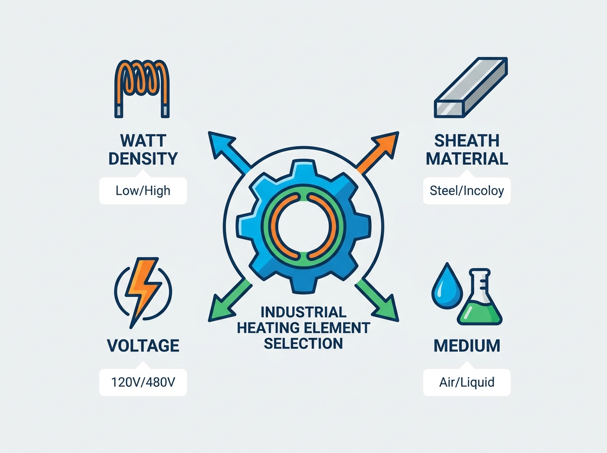
Premature heater failure causes massive disruptions in industrial processing facilities. Unplanned downtime stops production lines completely, while degraded fluid quality ruins entire batches of product. Equipment replacement costs drain maintenance budgets quickly. Specifying the right heater requires deep technical knowledge and field experience. A mismatch in watt density, sheath material, voltage, or physical fit creates severe operational problems. These engineering errors lead directly to rapid oxidation, fluid coking, or catastrophic thermal burnout.
You need a structured engineering framework to evaluate and select the correct specifications. We will guide you through this critical process. You must match the heater design to the target medium and required temperature. You must also account for environmental corrosiveness and physical installation constraints. Properly specified industrial electric heating elements ensure safe, efficient, and continuous operation. This guide provides the exact criteria you need to design and select a robust thermal system.
Medium Dictates Material: The chemical composition and flow rate of the fluid or gas being heated are the primary determinants for sheath material selection.
Watt Density is the Lifeline: Exceeding the maximum allowable watt density (W/in²) for a specific medium guarantees premature element failure through coking, scale buildup, or thermal runaway.
Physical Fit Dictates Heat Transfer: Tight mechanical tolerances (bore fit for cartridges, clamping force for band heaters) are critical to eliminating air gaps and optimizing heat transfer.
System Sizing Requires Precision: Accurate calculation of total wattage must account for initial heat-up time, maintenance temperature, environmental heat losses, and electrical configuration.
Controls Prevent Catastrophe: Proper integration of cold zones, high-limit temperature sensors, and appropriate lead terminations is non-negotiable for safe, long-term operation.
You must identify the exact chemical makeup of your target medium. Different fluids react uniquely to applied heat. Heating clean water requires different parameters than heating heavy asphalt or bunker fuel. Corrosive acids demand highly specialized protective barriers. You must also determine the concentration levels of any chemical solutions. Even trace amounts of chlorides can attack standard metals at elevated temperatures. Gas heating applications require precise knowledge of the gas composition, flow velocity, and moisture content.
You must distinguish between initial heat-up requirements and steady-state maintenance heating. Initial heat-up demands a high energy input to raise the medium from ambient to target temperature. This is known as the delta-T phase. Maintenance heating requires significantly less power. It only needs to replace heat lost to the environment or consumed by the process. Sizing a heater solely for heat-up can result in an oversized system. Oversized systems often short-cycle, which damages electrical contactors and degrades fluid quality.
Identify the exact chemical composition and concentration of the fluid or gas.
Determine the specific heat capacity and specific gravity of the medium.
Calculate the required delta-T (temperature rise) for the initial startup phase.
Measure the physical dimensions of the tank or vessel to determine maximum heater length.
Evaluate the ambient environmental conditions, including temperature extremes and moisture levels.
Fluid velocity directly impacts the ability of the element sheath to shed heat. High flow rates strip heat away from the sheath rapidly. This prevents localized boiling and keeps internal wire temperatures safe. Stagnant fluids absorb heat slowly. This causes the sheath temperature to spike rapidly. You must design your system to maintain adequate flow across all heated surfaces. In large tanks, this often requires mechanical agitators or circulation pumps.
The element's surface temperature must remain below the degradation point of the target medium. If the sheath gets too hot, oils will scorch and carbonize. This process is called coking. Coking creates an insulating layer of carbon on the heater. This insulation traps heat inside the element, leading to rapid internal failure. You must balance the power output with the fluid's ability to absorb heat safely.
Mechanical tolerances dictate heat transfer efficiency in solid heating applications. Air acts as a powerful thermal insulator. You must eliminate air gaps between the heater and the heated part. For cartridge heaters, you need extremely tight bore clearances. A loose fit traps air, causing the internal wire to overheat and melt. For band and strip heaters, you must apply proper torque and clamping pressure. Secure clamping forces the heater into direct contact with the metal surface. This maximizes conduction and extends heater life.
The internal resistance wire generates the actual heat. Nickel-Chromium (NiCr) and Iron-Chromium-Aluminum (FeCrAl) are the two primary alloys used. NiCr alloys, specifically 80/20 (80% Nickel, 20% Chromium), offer excellent high-temperature strength. They resist oxidation well and maintain structural integrity under cyclic operation. They are the standard choice for most industrial applications.
FeCrAl alloys, often known as Kanthal, provide higher electrical resistivity. They can operate at higher maximum temperatures than NiCr alloys. They form a protective aluminum oxide layer when heated. This layer provides exceptional oxidation resistance. However, FeCrAl alloys become brittle after their first heating cycle. This makes them susceptible to mechanical shock and vibration damage. You must choose the alloy based on your specific temperature targets and mechanical environment.
Copper sheaths provide excellent thermal conductivity. They are ideal for heating clean water and providing freeze protection. Copper is easy to form and relatively inexpensive. However, it has strict temperature limitations. It should not operate above 350°F (175°C). Copper is also highly susceptible to oxidation in open air. We rarely use copper in heavy industrial settings unless heating clean, non-corrosive water.
Carbon steel sheaths handle higher temperatures than copper. They are commonly used for heating asphalt, tar, and high-viscosity oils. They are also suitable for certain heat transfer fluids. Carbon steel can operate safely up to 750°F (400°C). However, it rusts quickly in moist environments. It offers zero resistance to corrosive chemicals. You must only use carbon steel in dry or strictly non-corrosive fluid applications.
Stainless steel provides a massive upgrade in corrosion resistance. Alloy 304 is the baseline standard for mildly corrosive environments. It works well in food processing, parts washing, and clean water applications. It resists oxidation up to 1200°F (650°C). However, 304 stainless is vulnerable to chloride attack. If your process water contains high chlorides, 304 will pit and fail.
Alloy 316 contains molybdenum. This addition significantly boosts its resistance to chlorides and harsh chemicals. It is the preferred choice for deionized water, medical equipment, and chemical processing. Alloy 321 contains titanium, which stabilizes the metal at high temperatures. It prevents carbide precipitation during welding. All these stainless alloys offer excellent thermal stability for standard industrial applications.
High-nickel alloys dominate extreme operating environments. Incoloy 800 and 840 offer superior oxidation and carburization resistance. They handle high-temperature air heating and superheated gases easily. They are the industry standard for hard water applications. Mineral scale does not adhere as strongly to Incoloy as it does to stainless steel. These alloys operate safely up to 1600°F (870°C).
Inconel 600 provides even greater high-temperature tolerance. It resists chloride-ion stress corrosion cracking completely. It maintains high mechanical strength at extreme temperatures. You should specify Inconel for the most demanding applications. It excels in corrosive gas streams and high-temperature chemical baths. These high-nickel materials ensure long-term reliability where standard metals fail rapidly.
Highly aggressive chemical baths destroy standard metals instantly. Electroplating tanks and hydrochloric acid baths require specialized protection. Titanium sheaths resist highly corrosive chloride solutions and nitric acid. They offer excellent durability but require careful handling during installation.
Fluoropolymer (PTFE) coatings provide the ultimate chemical resistance. PTFE jackets protect the internal metal sheath from virtually any acid or base. However, PTFE introduces severe engineering trade-offs. It is a poor thermal conductor. You must operate PTFE-coated heaters at extremely low watt densities. They are also physically fragile. You must protect them from mechanical impact and abrasion within the tank.
Sheath Material | Primary Applications | Max Operating Temp (°F) | Corrosion Resistance |
|---|---|---|---|
Copper | Clean water, freeze protection | 350 | Low |
Carbon Steel | Asphalt, heavy oils, heat transfer fluids | 750 | Low |
304 Stainless Steel | Food processing, parts washing | 1200 | Moderate |
316 Stainless Steel | Deionized water, mild chemicals | 1200 | High |
Incoloy 800/840 | Hard water, high-temp air, gases | 1600 | Very High |
Titanium | Electroplating, harsh acids | Varies | Extreme |
Watt density measures the heat output per square inch of the element's active surface area. It is the most critical specification for heater longevity. You calculate it by dividing the total wattage by the heated surface area. High watt densities generate intense heat in a small physical space. Low watt densities spread the heat over a larger area.
The physics of heat dissipation control element survival. Higher watt densities require a medium with high thermal conductivity. The fluid must flow rapidly to absorb the heat. If the fluid cannot absorb the heat fast enough, the sheath temperature spikes. This trapped heat forces the internal resistance wire to overheat. The wire will eventually melt, destroying the heater completely. You must match the watt density to the thermal properties of the medium.
Every fluid has a maximum safe watt density limit. Exceeding this limit guarantees failure. Clean water absorbs heat rapidly. It can handle high watt densities safely. Heavy oils absorb heat slowly. They require very low watt densities to prevent scorching.
Target Medium | Recommended Sheath Material | Maximum Watt Density (W/in²) |
|---|---|---|
Clean Water | Copper, 304 SS, Incoloy | 45 - 60 |
Light Oils & Degreasers | Steel, 304 SS | 20 - 30 |
Heavy Viscous Oils & Asphalt | Steel, 304 SS | 5 - 10 |
Air / Gas (Moving) | Incoloy, Finned Stainless | 10 - 30 (Velocity Dependent) |
Corrosive Chemical Baths | Titanium, PTFE Coated | 10 - 15 |
The choice of sheath material also limits the safe maximum watt density. Materials with lower maximum operating temperatures require lower watt densities. You must cross-reference the fluid limits with the material limits. Always design to the lowest limiting factor to ensure safety.
Exceeding recommended limits triggers destructive chemical reactions. In oil applications, excess heat causes coking. The oil breaks down chemically and bakes onto the sheath. This forms a hard, black carbon layer. In water applications, excess heat causes calcification. Dissolved minerals precipitate out and form hard scale on the metal.
Both scale and carbon deposits act as powerful thermal insulators. They trap heat inside the element. The sheath temperature rises rapidly to push heat through the scale. This drives up the internal wire temperature. The internal wire eventually reaches its melting point. The element burns out catastrophically. Proper watt density prevents these insulating layers from forming.
You must calculate the exact kilowatts (kW) needed for your process. This requires a standard thermodynamic calculation. You need to know the mass of the material being heated. You must know its specific heat capacity. You must define the required temperature differential (delta-T). Finally, you must set the allowable time for heat-up.
The basic formula calculates the theoretical energy required. However, real-world systems lose heat constantly. Heat escapes through tank walls, uninsulated piping, and open liquid surfaces. Ambient air exposure drains energy from the system. You must add a 20% safety margin to your theoretical calculation. This safety factor compensates for uncalculated heat losses and ensures the system reaches the target temperature reliably.
You must match the heater design to your available facility power. Small heaters often run on 120V or 240V single-phase power. Large industrial systems require higher voltages. Operating high-wattage heaters on low voltage draws massive amperage. This requires thick, expensive wiring and massive contactors.
Utilizing 480V three-phase power solves this problem. Three-phase power balances the electrical load across three distinct legs. It significantly reduces the required amperage for high-kW heaters. Lower amperage allows you to use smaller wire gauges and standard industrial controls. You must verify your facility's voltage and phase capacity before specifying the heater.
Verify the exact voltage available at the installation site.
Determine if the power supply is single-phase or three-phase.
Calculate the total amperage draw based on the required kW and available voltage.
Size all contactors, fuses, and wiring to handle 125% of the maximum continuous load.
The internal heating wire changes resistance as it heats up. Most alloys have a positive temperature coefficient of resistance. This means their electrical resistance increases as they get hot. A cold heater draws more amperage upon initial startup than it does during steady-state operation. You must account for this inrush current.
You must size your electrical infrastructure carefully. Contactors, wiring, and fuses must handle the startup amperage safely. They must also sustain the operating amperage continuously. Undersized wiring will overheat and create a severe fire hazard. Undersized contactors will weld shut, destroying temperature control. Always size electrical components based on the maximum possible amperage draw under cold startup conditions.
Threaded screw plug heaters thread directly into tank walls. They use standard NPT pipe threads. They are ideal for smaller vessels and tight spaces. They are easy to install and replace. However, their physical size limits their maximum wattage. You typically use them for lower-power applications.
Flanged heaters bolt onto matching nozzles on the tank. They accommodate dozens of individual heating elements on a single flange. They are designed for high-wattage, large-volume tanks. They handle high-pressure vessels easily. Flanged heaters deliver massive heat output for heavy industrial processes. You must ensure the tank nozzle matches the flange specifications exactly.
Circulation heaters heat fluids as they flow continuously through a pipe. The heating elements sit inside a pressure vessel. The fluid enters one end, absorbs heat, and exits the other. They provide precise temperature control for moving fluids. They are essential for heating fuel oils, corrosive chemicals, and process gases.
Internal baffle placement is critical for circulation heaters. Baffles force the fluid to flow back and forth across the elements. This optimizes fluid velocity and maximizes heat transfer. Baffles eliminate stagnant zones where fluid could overheat and degrade. You must specify the correct baffle arrangement based on your fluid's viscosity and flow rate.
Cartridge heaters are cylindrical elements designed for insertion into drilled holes. They heat solid metal parts like platens, dies, and molds. They provide highly localized, intense heat. You must machine the receiving hole to exact tolerances to ensure proper heat transfer.
Band heaters clamp onto cylindrical surfaces. They are used extensively on plastic injection molding barrels and pipe systems. Strip heaters bolt onto flat metal plates or tank walls. Both band and strip heaters rely entirely on conductive heat transfer. You must tighten them securely to eliminate air gaps and prevent premature failure.
The cold zone is the unheated portion of the element near the connection terminal. It prevents the electrical connections from overheating. The cold zone must extend past tank insulation and thick vessel walls. It must also extend above any sludge layers at the bottom of the tank. If the heated section sits in sludge or insulation, it will burn out immediately.
Tubular elements are often bent to fit specific tank dimensions. However, you must respect minimum bending radii. Bending the element too sharply crushes the internal dielectric insulation (MgO). This compaction forces the internal wire into the metal sheath. This creates a direct electrical short circuit. You must follow the manufacturer's bending guidelines strictly to maintain internal electrical isolation.
You must select the correct physical dimensions for your application. This includes the overall length, diameter, and active heated length. You must also choose the right lead wire insulation. Fiberglass insulation withstands high ambient temperatures but absorbs moisture. PTFE insulation resists moisture and harsh chemicals perfectly. Silicone rubber provides excellent flexibility and moderate temperature resistance.
Termination styles dictate how you connect the power wiring. Screw terminals provide secure, heavy-duty connections. Spade lugs offer quick installation. Flexible leads allow for movement and vibration. You must also specify the correct environmental seal. Epoxy seals block moisture in standard environments. Ceramic-to-metal hermetic seals provide absolute protection against moisture ingress in extreme conditions. Protecting the internal magnesium oxide (MgO) insulation from moisture is critical for element survival.
Poor circulation destroys heaters rapidly. If fluid stops moving, localized boiling occurs. The fluid degrades, and the heater overheats. Incorrect element placement within a process tank creates dead zones. You must position the heater where natural convection or mechanical agitation ensures constant fluid movement across the sheath.
You must implement strict predictive maintenance schedules. Physical descaling removes hard mineral deposits from the sheath. Chemical cleaning dissolves baked-on carbon and organic residues. You must monitor sheath integrity regularly. Inspect the elements for pitting, cracking, or severe discoloration. Catching scale buildup early prevents catastrophic thermal burnout and extends equipment life significantly.
Accurate temperature control requires precise sensor placement. You must place process temperature sensors (thermocouples or RTDs) directly in the active fluid stream. Do not place them too close to the heater, or they will read artificially high. Connect these sensors to a PID loop controller. The PID controller pulses power to the heater, maintaining a stable process temperature without severe overshooting.
You must mandate the use of a secondary, independent high-limit thermocouple. Attach this sensor directly to the heater sheath. Wire it to a dedicated high-limit controller. If fluid levels drop or flow stops entirely, the sheath temperature will spike instantly. The high-limit controller will cut power before catastrophic failure occurs. This independent safety system is an absolute requirement for safe industrial heating.
Selecting the right industrial electric heating element is not simply a matter of choosing the highest wattage available. Long-term performance depends on achieving the correct balance between heat output, material compatibility, physical installation requirements, and process operating conditions.
A reliable heating system begins with understanding the application environment. The heating medium, flow characteristics, temperature requirements, electrical configuration, and mechanical constraints all influence the final heater design. Selecting the wrong sheath material, exceeding the allowable watt density, or ignoring heat transfer limitations can quickly result in scale buildup, coking, insulation failure, and unexpected production downtime.
The most effective approach is to treat the heating element as a complete engineered component within the thermal system. Proper sizing, optimized watt density, suitable metallurgy, accurate temperature control, and independent safety protection work together to maximize equipment lifespan and maintain consistent process performance.
At HOTOHEAT, we design and manufacture customized industrial electric heating solutions based on specific application requirements. From material selection and watt density optimization to heater configuration and control integration, our engineering team helps customers develop reliable heating systems for demanding industrial environments.
A: Premature burnout is usually caused by exceeding the maximum allowable watt density for the medium. This leads to scale buildup or coking, which insulates the sheath. The trapped heat forces the internal resistance wire to melt. Poor fluid circulation and incorrect voltage application also cause rapid failure.
A: Use 304 or 316 stainless steel for clean, deionized, or mildly corrosive water. Choose Incoloy 800 or 840 if you are heating hard water. Mineral scale does not adhere as strongly to Incoloy, making it much more durable in high-mineral environments.
A: The cold zone is the unheated section near the electrical terminals. It ensures that the active heating section is fully submerged in the fluid. If the heated section sits inside the tank wall, insulation, or sludge, it cannot dissipate heat and will burn out immediately.
A: No. Applying 480V to a heater designed for 240V will quadruple its wattage output. This massive increase in power will cause the internal resistance wire to melt almost instantly, destroying the heater and creating a severe electrical hazard.
A: A high-limit sensor is an independent safety device attached directly to the heater sheath. It monitors the actual metal temperature. If fluid levels drop or flow stops, it detects the rapid temperature spike and cuts power before the element melts or causes a fire.
A: Higher fluid velocity strips heat away from the element sheath faster. This allows you to safely use a higher watt density. Stagnant fluids require much lower watt densities to prevent localized boiling and sheath overheating.
A: Threaded heaters screw into standard pipe fittings and are used for smaller, lower-wattage applications. Flanged heaters bolt onto tank nozzles, accommodate many elements, and are designed for high-wattage, large-volume industrial heating.